Thursday

How to Keep Trucks from Hitting or Becoming Stuck Under Overpasses

http://www.pantron.com/us/pantron-complete-set.htmlOperators of large trucks sometimes do not accurately measure the height of the vehicle or the extra height of the load that they are carrying. When they drive these trucks under a bridge or overpass that has a lower maximum height requirement, these trucks either strike the overpass or, in some cases, the vehicle becomes lodged beneath the overpass.

Excessive traffic congestion and the financial burden of removing lodged trucks and repairing overpasses is a good incentive to apply a relatively simple and inexpensive means of warning drivers if the load that they carry exceeds the maximum height for a bridge or overpass.

Purchase a set of industrial photoelectric sensors that use an amplifier with an internal manual relay.  These photoelectric sensors should be positioned in an opposed-mode configuration (or through-beam) so that the transmitting eye is located on one side of the lane and the receiver is on the opposing side.  The photo eyes should face one another so that the infrared beam projects across the roadway.  The infrared beam should be positioned so that it is horizontal to the road surface and at a height that is just below the maximum allowable vehicle height of the overpass.  When the beam is broken by a vehicle or by cargo, it will trigger a signal from the photoelectric amplifier.  These photoelectric sensors should be located far enough from the overpass, that they will detect the over-sized vehicle in time to warn the driver to exit the roadway.

Connect the relay from the photoelectric amplifier to a set of flashing lights and use the proper signage to alert the driver and provide them with simple instructions, for example, "WARNING MAXIMUM HEIGHT EXCEEDED - TAKE EXIT WHEN LIGHTS ARE FLASHING!"  Though, this solution is a simple one and very inexpensive, the benefits will be quickly realized.

Related products and information
Infrared photoelectric sensors for outdoor applcations in bright sunlight
Infrared amplifer with manual gain for use with photoelectric sensors
Polarized filter attachment for infrared photoelectric sensors

Wednesday

How to Test Whether a Sensor has a PNP or NPN Type Output Using a Multi meter

If you are replacing a 3 wire sensor which operates on DC voltage, it is important to know whether the sensor's output is a PNP or NPN type. Often this information is printed on the sensor itself, but it is not uncommon for it to be scratched off over a long period of time.

Set the multi meter to DC voltage. This is indicated by either the letters "VDC" or "DCV" or by a symbol which looks like 3 dashed lines over a solid line. There are usually several levels within the DC voltage setting. Choose the "600" level.

The power will need to be ON to perform this test, so use caution when attempting the following. Connect two of the sensor wires to the power supply. If the color combination of the wires is blue, black, and brown, then normally, the blue wire connects to 0v and the brown wire connects to positive volts. Touch the black meter probe to the 0V wire of the sensor. Connect the red meter probe to the signal output wire of the sensor. This wire is normally black. The meter should read "0."

Force the sensor to output. If it is a photoelectric sensor, block the photoelectric beam. If it is an inductive proximity switch, introduce a small piece of metal in front of the sensor. For an ultrasonic sensor or a capacitive sensor, you can just use your hand to make the sensor output. Be sure that the sensor is detecting the object. Many sensors have a small LED that illuminates when the sensor detects it's target.

Watch the meter display as you force the sensor to output. If the readout changes to a number between 10 and 30, then the sensor output is a PNP type, also known as "sourcing." If the meter display remains at "0", then the sensor output is an NPN type, also known as "sinking."

If you believe that the sensor is NPN, there is an additional test that may be done to confirm. Remove the meter probes from the wires. Now place the red meter probe on the positive voltage sensor wire, normally a brown wire. Touch the black meter probe to the signal output wire of the sensor, normally black. When the sensor does not detect it's target, the meter display should read between 10 and 30. When the sensor senses an object, the display should drop to "0." This will confirm that the sensor has an NPN type output.

Monday

How to Measure the Level of Material in a Large Bin or Hopper

http://www.pantron.com/us/pantron-complete-set.html
Let's say you have a large bin or hopper and you regularly fill it with wood chips or powder or even liquid. How can you accurately measure the level in the bin?  In applications where it is necessary to measure the level of material in a large collection bin, there is not always an obvious way. This article will describe one method, using an ultrasonic sensor.

Purchase an industrial ultrasonic sensor (uses sound waves) with a range long enough to bounce from the top of the bin down to the lowest possible level of the material, or at least the lowest level that you care to measure. Be sure to select an ultrasonic sensor with an analog output.  Be aware that all ultrasonic sensors have a "blind zone" beginning at the face of the sensor and extending to various distances away. For this reason, the material to be measured should never be allowed to enter this "blind zone" because accurate measurement cannot take place in this range.  Also note that ultrasonic sensors are affected by drastic changes in temperature and may need to be re-calibrated occasionally.

Install the ultrasonic sensor in the top of the bin pointing downward so that it faces the material in the bin. The analog output from the sensor will need to interface with the PLC or computer so that the reading may be interpreted and any necessary functions may take place when the level reaches certain points.

Empty the bin and take note of the output from the sensor. Then, fill the bin to the maximum desired level and take another reading from the sensor. Now you have your high and low margins. You can program certain things to happen when the material hits a certain level, for instance, when the level of water in a bin reaches the top, the pump that supplies the water shuts off until the water is lowered again to another predetermined level.

Related products and information
Ultrasonic sensors for level control

Friday

How to Use Sensors to Detect that Contents are Missing from Foil Wrappers

http://www.pantron.com/us/pantron-complete-set.html
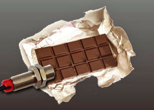
An application to detect if the contents of a foil wrapper are missing is fairly easy to solve using two sets of industrial grade high-powered infrared photoelectric sensors.

Many industries use foil wrappers to package products. For quality control, it is a good idea to have a system capable of automatically detecting when the contents of those wrappers are missing. Some companies use human beings to manually pick and choose wrappers, which is tedious, and not very efficient. There is a solution that really works; infrared photoelectric sensors.

Position one set of infrared photoelectric sensors in a through-beam configuration, so that the foil wrapper will move between the sensors at a given point. Adjust the sensitivity of the infrared photoelectric sensors so that they will detect the foil wrapper whether it is full or empty. The sensors should be at their most sensitive setting for this. The output from this set of sensors will report to the PLC to let it know when a foil wrapper is present.

Position the second set of infrared photoelectric sensors beside the first set, also in a through-beam configuration and facing the same direction. Be sure that the sensors are set to different frequencies to avoid cross-talk between the two sets. This set of sensors should be adjusted to its least sensitive setting. In other words, crank the gain setting to the max. Assuming that the photoelectric sensors being used are industrial grade, they should be able to see through an empty wrapper easily, but not one containing product. This set should also report to the PLC.

Now, you have two infrared beams of light striking the foil wrapper as it passed. One is used as a reference to let the PLC know when a foil wrapper is present. The second set of sensors lets the PLC know when a foil wrapper is missing its expected contents. This system is very reliable and is in use at a number of companies worldwide.


Related products and information
Stainless-steel infrared photoelectric sensors for packaging applications

Wednesday

How to Replace an Air Pressure Hose Switch with Non-contact Photoelectric Sensors

Businesses which use hoses attached to pressure sensors to detect vehicles would benefit from upgrading this system to an infrared photoelectric sensor system.

If you are old enough to remember full-service gas stations, you probably remember that when a car or truck drove up, the tires would run over a long hose and a bell would sound alerting the attendant that a customer had arrived. The same principle of using a hose and air pressure to activate a switch is still used by many companies in a number of ways.

Air hoses may be used to conduct a traffic count for demographic studies by stretching the hose across a lane of traffic. They are also used to open automatic doors and gates. The basic idea behind the operation of these devices is simple. When an object applies pressure to the hose, the air is forced to one end. The pressure of the moving air moves a switch. This switch may be used to control almost any electronic device.

The problem with the air hose is that over time, the hose and the mechanical switch wear out. Also, it is very easy for the hose to be moved out-of-place. An alternative to this system is to use an industrial grade infrared photoelectric sensor system. Using non-contact photoelectric sensors provides an installation that is both tidy and easy to maintain. Because there is no physical contact with the detected object, there are no moving parts to wear out.

Replacing an air hose system with an industrial grade infrared photoelectric sensor system is easy. The photoelectric controller (also referred to as an amplifier) replaces the air hose controller. Many photoelectric controllers have built-in relay switches, making the transition simple. The infrared photoelectric sensors may be placed in a through beam configuration or diffuse proximity (both sensors on the same side) configuration depending on space and wiring requirements. The transition from the old style air hoses to the new photoelectric sensors is easy, quick, and a wise investment.

Related products and information
Infrared photoelectric sensors for driveway applications
Infrared photoelectric amplifier for use with photoelectric sensors
Loop detector and in-ground inductive loop for sensing vehicles