Showing posts with label Sensor. Show all posts

Wednesday

Inductive Proximity Switches for Sensing Metal Objects in Extemely HOT or COLD Areas

http://www.pantron.com/us/ege-inductive-proximity-switches.html
The German manufacturer, EGE Elektronik, offers special inductive proximity switches for high temperature applications. Focus is on TROPICAL switches which exceed IP 69K with a temperature range up to +120 °C and is optimally suited for corrosive environments.

Even higher temperature switches up to 160 °C are also offered.

EGE's highest temperature resistant sensors can be used in extremely HOT environments up to 250 °C.  These models are available with armored cables and external amplifiers.

On the lower end of the temperature scale are the POLAR switches that thrive in -60 °C.

Large switching distances up to 170 mm and sensors resistant to rolling oils made from PTFE, PP or PEEK are also available for the food industry. Intrinsically safe ex-classified sensors according to ATEX and compact dust-EX and gas-EX sensors complete the product program.

The "demanding environment" sensors offered by EGE are specially designed for harsh environments in which sensors are exposed to high electrical, electromagnetic or mechanical stresses. Stresses are not always included in customary inspection and test methods in the way that they develop in different production environments. Therefore, EGE has developed special test methods that are better suited to the use of sensors in critical applications. This has resulted in sensor designs that are suitable for use in almost any environment.

Tuesday

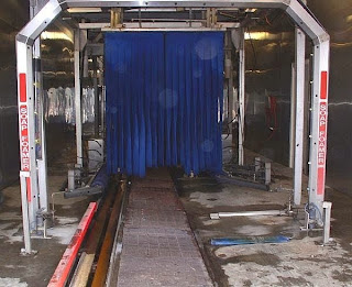
How to Install and Maintain Photoeye Sensors for In-bay Automatic Car Washes

http://www.pantron.com/us/applications-carwash.html
In-bay automatic car washes rely on sensors to control the car wash equipment. Without sensors, the wash computer would assume that every vehicle is the same length, height, and width. Applications for sensors include starting the wash, measuring vehicles, and controlling the opening and closing of doors. Photoelectric sensors have become a preferred method of detection due to their performance and ease of use. Proper installation and regular maintenance will ensure uninterrupted performance from the photoelectric sensors.

The first thing to consider when choosing a sensor for an automatic car wash is the type of application that the sensor will be used in. Photoelectric sensor systems typically consist of, at very least, an infrared transmitter, an infrared receiver, and in high-powered systems, an external amplifier. For the simple detection of a vehicle, the photo eyes are positioned on either side of the car wash. The transmitter photo eye emits an infrared beam of light across the bay that is detected by the receiver photo eye. When the infrared beam is interrupted by a vehicle, a signal is sent to the equipment to perform the desired application. This may be starting the equipment, measuring or profiling the vehicle, or simply opening and closing the doors. Usually, one sensor is mounted high, while the other is mounted low so that the sensors form a diagonal line to the ground. This causes the beam to pass through the area where the largest portion of the vehicle will pass and helps to reduce false signals. Mechanical treadle plates that are used to position the vehicle may be replaced by photoelectric sensing systems.
http://www.pantron.com/us/pantron-photoeyes.html
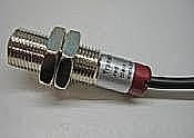
The body of the sensor should be durable and designed to withstand the harsh conditions of the wash. There are sensor bodies available in plastic, nickel-plated brass, and stainless-steel to meet the requirements of the car wash environment. A simple infrared sensor like the ones used in a residential garage door application are not designed to withstand the conditions in a car wash and should be avoided in this type of application because they lack the proper sealing. For the car wash environment select a sensor with an IP67 rating. This rating is used to inform the end-user that the sensor is sealed in a way that will not allow the internal circuits to be damaged by water spray or submersion. The range of the sensor is important for two reasons. It is much easier to mount the sensors in a place where they will not be hit if they have a long enough sensing distance. A strong infrared beam will also assist in penetrating the steam, mist, and soap that are present while the wash is running and will provide fewer false signals and the resulting down-time.

Required maintenance to photoelectric sensors is easy, and requires very little time. Check the alignment of the photo eyes using a length of string or wire long enough to pull in a line between the sensors. This line should be parallel with the sides of both sensors. If you are using a set of photoelectric sensors that uses an external amplifier, periodically check to be sure that the seal on the enclosure box is still intact and that no water has penetrated into the inside of the box.

If you have problems with the photoelectric controls, determine the nature of the problem. Are they giving an intermittent output that flickers? Do the sensors report an output all the time? Is it impossible to break the beam between the photo eyes? Once you determine the nature of the problem, it is then easier to isolate the cause. If there is a flickering output, check the alignment of the photo eyes. Next check to be sure the photoelectric system is turned high enough. (On amplified systems, this setting is located on the amplifier, inside the water-tight enclosure.) If both of these things appear normal, check for corrosion at any points where the cable has been cut and spliced. If you find corrosion, be sure to cut and reconnect the wires using a soldered connection and heat-shrink tubing. This will help seal out moisture from the connection. If you still see flickering from the output of the photo eyes, check to be sure all wires that should be grounded are connected to ground. The wires from the photoelectric controls should not share the same conduit as the wires from any motor controls.

If a constant output is the problem, check both photo eyes for obstructions. Be sure trash hasn't blown in front of the eyes and found a permanent home in the path of the beam. Alignment may also be an issue, but if they are out of alignment far enough to give a solid output signal, then this should be fairly obvious to the naked eye. Next, look closely at the face of the photo eyes. Check for visible cracks or bad abrasions. Even an IP67 sealed photo eye can be rendered useless if a large enough crack forms in the face of the sensor, thereby allowing moisture to breach the internal circuits of the photo eyes.

If it appears that the infrared beam between the eyes is impossible to break, the cause is one of several things. The first is simply that the intensity of the infrared beam is too strong and that it is literally not being blocked as the vehicle passes. Reflections on the wet walls contribute to this problem also. Try turning the strength of the system down a little. If this doesn't work, check the alignment of the photo eyes. Maybe the photo eyes see each other at an angle and when the vehicle passes through, the beam is not being broken at that angle.


Related products and information
Infrared photoelectric sensors for car washes
Infrared photoelectric amplifier for use with photoelectric sensors

Sunday

How to Automate a Haunted House Using Sensors

http://www.pantron.com/us/applications-haunted-house.html
You've built a creepy haunted house and it's the scariest one around. How do you take it to the next level? Automate it using non-contact infrared photoelectric sensors to control electronic scare devices.

Haunted houses are designed to be very creepy and with enough volunteers, they may be loaded with frights around every corner. What if there are not enough volunteers available to haunt the house? Infrared photoelectric sensors are the perfect device to detect guests and to trigger electronic gadgets, such as noise makers or motorized animatronic characters, giving visitors a scare they won't soon forget.

Sensors are used every day in various industries ranging from food processing to automotive assembly lines. Some of the top commercial haunted houses in the country are now using the very same sensors to automate their haunted attractions, providing a far creepier presentation. Industrial sensors are available to the general public for less money than you might expect, giving the average Joe an opportunity to built a haunted house that rivals even the ones presented by major theme parks.

The easiest type of photoelectric sensor to use in a haunted house attraction is one that uses a mechanical relay switch. This type of sensor is as easy to wire and operate as a light switch. Also be sure that the photoelectric sensors use infrared light and do not display a visible light which would draw attention to them. Arrange the photoelectric sensors across from each other in a hallway or door jamb, or anywhere that a guest will pass between them. The guest will break the infrared beam of light, causing the mechanical relay switch in the photoelectric controller to close, which will provide power to a noise maker or animatronic device. Each time a guest passes the sensors, the same action will occur repeatedly without operator intervention. This allows volunteers in the haunted house to spend time mingling with the guests and not hiding behind walls, just making noise.

Related products and information
Infrared photoelectric sensors and timed amplifiers for haunted houses
Amusement park applications

Monday

How to Measure the Level of Material in a Large Bin or Hopper

http://www.pantron.com/us/pantron-complete-set.html
Let's say you have a large bin or hopper and you regularly fill it with wood chips or powder or even liquid. How can you accurately measure the level in the bin?  In applications where it is necessary to measure the level of material in a large collection bin, there is not always an obvious way. This article will describe one method, using an ultrasonic sensor.

Purchase an industrial ultrasonic sensor (uses sound waves) with a range long enough to bounce from the top of the bin down to the lowest possible level of the material, or at least the lowest level that you care to measure. Be sure to select an ultrasonic sensor with an analog output.  Be aware that all ultrasonic sensors have a "blind zone" beginning at the face of the sensor and extending to various distances away. For this reason, the material to be measured should never be allowed to enter this "blind zone" because accurate measurement cannot take place in this range.  Also note that ultrasonic sensors are affected by drastic changes in temperature and may need to be re-calibrated occasionally.

Install the ultrasonic sensor in the top of the bin pointing downward so that it faces the material in the bin. The analog output from the sensor will need to interface with the PLC or computer so that the reading may be interpreted and any necessary functions may take place when the level reaches certain points.

Empty the bin and take note of the output from the sensor. Then, fill the bin to the maximum desired level and take another reading from the sensor. Now you have your high and low margins. You can program certain things to happen when the material hits a certain level, for instance, when the level of water in a bin reaches the top, the pump that supplies the water shuts off until the water is lowered again to another predetermined level.

Related products and information
Ultrasonic sensors for level control

Friday

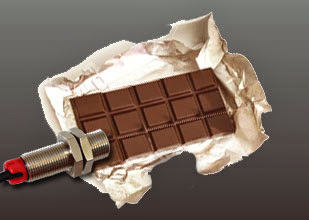
How to Use Sensors to Detect that Contents are Missing from Foil Wrappers

http://www.pantron.com/us/pantron-complete-set.html
An application to detect if the contents of a foil wrapper are missing is fairly easy to solve using two sets of industrial grade high-powered infrared photoelectric sensors.

Many industries use foil wrappers to package products. For quality control, it is a good idea to have a system capable of automatically detecting when the contents of those wrappers are missing. Some companies use human beings to manually pick and choose wrappers, which is tedious, and not very efficient. There is a solution that really works; infrared photoelectric sensors.

Position one set of infrared photoelectric sensors in a through-beam configuration, so that the foil wrapper will move between the sensors at a given point. Adjust the sensitivity of the infrared photoelectric sensors so that they will detect the foil wrapper whether it is full or empty. The sensors should be at their most sensitive setting for this. The output from this set of sensors will report to the PLC to let it know when a foil wrapper is present.

Position the second set of infrared photoelectric sensors beside the first set, also in a through-beam configuration and facing the same direction. Be sure that the sensors are set to different frequencies to avoid cross-talk between the two sets. This set of sensors should be adjusted to its least sensitive setting. In other words, crank the gain setting to the max. Assuming that the photoelectric sensors being used are industrial grade, they should be able to see through an empty wrapper easily, but not one containing product. This set should also report to the PLC.

Now, you have two infrared beams of light striking the foil wrapper as it passed. One is used as a reference to let the PLC know when a foil wrapper is present. The second set of sensors lets the PLC know when a foil wrapper is missing its expected contents. This system is very reliable and is in use at a number of companies worldwide.


Related products and information
Stainless-steel infrared photoelectric sensors for packaging applications

Sunday

How to Measure Length and Diameter of an Object Travelling on a Conveyor

An application which requires an object to be measured for length and diameter as it travels along a conveyor belt may be solved using two types of sensors and a PLC.

Position a set of photoelectric sensors in a through-beam configuration so that the infrared beam crosses the conveyor. The object to be detected should break the beam as it travels. The photoelectric sensors will be used to measure the length of the object and also to trigger the measurement of the diameter by the ultrasonic sensor.

The ultrasonic sensor should be positioned above the conveyor facing downward and it should be well out of striking distance. The analog output from the ultrasonic sensor will be sent to the PLC, which should be programmed to calculate the diameter of the post based upon the sensor’s output.

The output from the photoelectric sensor actually serves two purposes. First, it will send a signal to the PLC indicating that the object is present. The PLC will then acknowledge the output from the ultrasonic sensor and begin its calculation. At the same time, the photoelectric sensors will help the PLC determine the length of the object using a calculation based upon the speed of the conveyor and the amount of time that the photoelectric sensors are blocked.

Though it sounds complicated, the hardest part of the application is the programming of the PLC, which should only be done by a trained professional. The benefits of using this equipment to solve the application are that the sensors are easy to install and they perform efficiently and reliably. Both measurements are done without physically contacting the object, so there are no moving parts to wear down.

Related products and information
Infrared photoelectric sensors for conveyor applications
Infrared photoelectric multiplexer for mutiple sets of photoelectric sensors

Saturday

How to Connect a Three-wire DC Sensor to a PLC

An application calls for a three-wire DC sensor to report to a PLC. How should they be connected together?  Check the input card of the PLC and find the voltage rating. Does it operate on DC voltage? Also determine whether the input needs to be sinking (NPN) or sourcing (PNP.) Look at the sensor and make sure the voltage rating and PNP / NPN type is the same. If there is a mismatch, refer to the manufacturer's instructions for both devices to determine compatibility.

If the PLC's input card is rated for DC voltage and it is a sinking (NPN) type input and also if the sensor operates on DC voltage in the same range and its output is sinking (NPN), then the two should be compatible. Connect the PLC to the power supply, but do not turn the power supply ON yet. Then connect the sensor's positive source voltage wire, which is normally brown, to the positive terminal of the power supply. Connect the negative or neutral sensor wire, normally blue, to the power supply as well, but on the negative terminal. Then connect the sensor's signal wire, normally black, to the PLC input card at the number address that you will assign as the sensor in the PLC program. When the sensor is activated, it will connect the PLC output to neutral or ground, which the PLC will interpret as a "true" condition and respond as programmed.

If the PLC's input card is rated for DC voltage and it is a sourcing (PNP) type input and also if the sensor operates on DC voltage in the same range and its output is sourcing (PNP), then the two should be compatible. Connect the PLC to the power supply, but do not turn the power supply ON yet. Then connect the sensor's positive source voltage wire, which is normally brown to the positive terminal of the power supply. Connect the negative or neutral sensor wire, normally blue, to the power supply as well, but on the negative terminal. Then connect the sensor's signal wire, normally black, to the PLC input card at the number address that you will assign as the sensor in the PLC program. When the sensor is activated, it will connect the PLC output to the positive terminal of the power supply, which the PLC will interpret as a "true" condition and respond as programmed.