Let's say you have a large bin or hopper and you regularly fill it with wood chips or powder or even liquid. How can you accurately measure the level in the bin? In applications where it is necessary to measure the level of material in a large collection bin, there is not always an obvious way. This article will describe one method, using an ultrasonic sensor.
Purchase an industrial ultrasonic sensor (uses sound waves) with a range long enough to bounce from the top of the bin down to the lowest possible level of the material, or at least the lowest level that you care to measure. Be sure to select an ultrasonic sensor with an analog output. Be aware that all ultrasonic sensors have a "blind zone" beginning at the face of the sensor and extending to various distances away. For this reason, the material to be measured should never be allowed to enter this "blind zone" because accurate measurement cannot take place in this range. Also note that ultrasonic sensors are affected by drastic changes in temperature and may need to be re-calibrated occasionally.
Install the ultrasonic sensor in the top of the bin pointing downward so that it faces the material in the bin. The analog output from the sensor will need to interface with the PLC or computer so that the reading may be interpreted and any necessary functions may take place when the level reaches certain points.
Empty the bin and take note of the output from the sensor. Then, fill the bin to the maximum desired level and take another reading from the sensor. Now you have your high and low margins. You can program certain things to happen when the material hits a certain level, for instance, when the level of water in a bin reaches the top, the pump that supplies the water shuts off until the water is lowered again to another predetermined level.
Related products and information
Ultrasonic sensors for level control
Monday
Friday
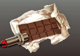
How to Use Sensors to Detect that Contents are Missing from Foil Wrappers
An application to detect if the contents of a foil wrapper are missing is fairly easy to solve using two sets of industrial grade high-powered infrared photoelectric sensors.
Many industries use foil wrappers to package products. For quality control, it is a good idea to have a system capable of automatically detecting when the contents of those wrappers are missing. Some companies use human beings to manually pick and choose wrappers, which is tedious, and not very efficient. There is a solution that really works; infrared photoelectric sensors.
Position one set of infrared photoelectric sensors in a through-beam configuration, so that the foil wrapper will move between the sensors at a given point. Adjust the sensitivity of the infrared photoelectric sensors so that they will detect the foil wrapper whether it is full or empty. The sensors should be at their most sensitive setting for this. The output from this set of sensors will report to the PLC to let it know when a foil wrapper is present.
Position the second set of infrared photoelectric sensors beside the first set, also in a through-beam configuration and facing the same direction. Be sure that the sensors are set to different frequencies to avoid cross-talk between the two sets. This set of sensors should be adjusted to its least sensitive setting. In other words, crank the gain setting to the max. Assuming that the photoelectric sensors being used are industrial grade, they should be able to see through an empty wrapper easily, but not one containing product. This set should also report to the PLC.
Now, you have two infrared beams of light striking the foil wrapper as it passed. One is used as a reference to let the PLC know when a foil wrapper is present. The second set of sensors lets the PLC know when a foil wrapper is missing its expected contents. This system is very reliable and is in use at a number of companies worldwide.
Related products and information
Stainless-steel infrared photoelectric sensors for packaging applications
Many industries use foil wrappers to package products. For quality control, it is a good idea to have a system capable of automatically detecting when the contents of those wrappers are missing. Some companies use human beings to manually pick and choose wrappers, which is tedious, and not very efficient. There is a solution that really works; infrared photoelectric sensors.
Position one set of infrared photoelectric sensors in a through-beam configuration, so that the foil wrapper will move between the sensors at a given point. Adjust the sensitivity of the infrared photoelectric sensors so that they will detect the foil wrapper whether it is full or empty. The sensors should be at their most sensitive setting for this. The output from this set of sensors will report to the PLC to let it know when a foil wrapper is present.
Position the second set of infrared photoelectric sensors beside the first set, also in a through-beam configuration and facing the same direction. Be sure that the sensors are set to different frequencies to avoid cross-talk between the two sets. This set of sensors should be adjusted to its least sensitive setting. In other words, crank the gain setting to the max. Assuming that the photoelectric sensors being used are industrial grade, they should be able to see through an empty wrapper easily, but not one containing product. This set should also report to the PLC.
Now, you have two infrared beams of light striking the foil wrapper as it passed. One is used as a reference to let the PLC know when a foil wrapper is present. The second set of sensors lets the PLC know when a foil wrapper is missing its expected contents. This system is very reliable and is in use at a number of companies worldwide.
Related products and information
Stainless-steel infrared photoelectric sensors for packaging applications
Labels:
automation,
contents,
detect,
electric,
electronic,
foil,
infrared,
missing,
photoelectric,
photoeye,
sense,
Sensor,
wrapper
Wednesday
How to Replace an Air Pressure Hose Switch with Non-contact Photoelectric Sensors
Businesses which use hoses attached to pressure sensors to detect vehicles would benefit from upgrading this system to an infrared photoelectric sensor system.
If you are old enough to remember full-service gas stations, you probably remember that when a car or truck drove up, the tires would run over a long hose and a bell would sound alerting the attendant that a customer had arrived. The same principle of using a hose and air pressure to activate a switch is still used by many companies in a number of ways.
Air hoses may be used to conduct a traffic count for demographic studies by stretching the hose across a lane of traffic. They are also used to open automatic doors and gates. The basic idea behind the operation of these devices is simple. When an object applies pressure to the hose, the air is forced to one end. The pressure of the moving air moves a switch. This switch may be used to control almost any electronic device.
The problem with the air hose is that over time, the hose and the mechanical switch wear out. Also, it is very easy for the hose to be moved out-of-place. An alternative to this system is to use an industrial grade infrared photoelectric sensor system. Using non-contact photoelectric sensors provides an installation that is both tidy and easy to maintain. Because there is no physical contact with the detected object, there are no moving parts to wear out.
Replacing an air hose system with an industrial grade infrared photoelectric sensor system is easy. The photoelectric controller (also referred to as an amplifier) replaces the air hose controller. Many photoelectric controllers have built-in relay switches, making the transition simple. The infrared photoelectric sensors may be placed in a through beam configuration or diffuse proximity (both sensors on the same side) configuration depending on space and wiring requirements. The transition from the old style air hoses to the new photoelectric sensors is easy, quick, and a wise investment.
Related products and information
Infrared photoelectric sensors for driveway applications
Infrared photoelectric amplifier for use with photoelectric sensors
Loop detector and in-ground inductive loop for sensing vehicles
If you are old enough to remember full-service gas stations, you probably remember that when a car or truck drove up, the tires would run over a long hose and a bell would sound alerting the attendant that a customer had arrived. The same principle of using a hose and air pressure to activate a switch is still used by many companies in a number of ways.
Air hoses may be used to conduct a traffic count for demographic studies by stretching the hose across a lane of traffic. They are also used to open automatic doors and gates. The basic idea behind the operation of these devices is simple. When an object applies pressure to the hose, the air is forced to one end. The pressure of the moving air moves a switch. This switch may be used to control almost any electronic device.
The problem with the air hose is that over time, the hose and the mechanical switch wear out. Also, it is very easy for the hose to be moved out-of-place. An alternative to this system is to use an industrial grade infrared photoelectric sensor system. Using non-contact photoelectric sensors provides an installation that is both tidy and easy to maintain. Because there is no physical contact with the detected object, there are no moving parts to wear out.
Replacing an air hose system with an industrial grade infrared photoelectric sensor system is easy. The photoelectric controller (also referred to as an amplifier) replaces the air hose controller. Many photoelectric controllers have built-in relay switches, making the transition simple. The infrared photoelectric sensors may be placed in a through beam configuration or diffuse proximity (both sensors on the same side) configuration depending on space and wiring requirements. The transition from the old style air hoses to the new photoelectric sensors is easy, quick, and a wise investment.
Related products and information
Infrared photoelectric sensors for driveway applications
Infrared photoelectric amplifier for use with photoelectric sensors
Loop detector and in-ground inductive loop for sensing vehicles
Sunday
How to Measure Length and Diameter of an Object Travelling on a Conveyor
An application which requires an object to be measured for length and diameter as it travels along a conveyor belt may be solved using two types of sensors and a PLC.
Position a set of photoelectric sensors in a through-beam configuration so that the infrared beam crosses the conveyor. The object to be detected should break the beam as it travels. The photoelectric sensors will be used to measure the length of the object and also to trigger the measurement of the diameter by the ultrasonic sensor.
The ultrasonic sensor should be positioned above the conveyor facing downward and it should be well out of striking distance. The analog output from the ultrasonic sensor will be sent to the PLC, which should be programmed to calculate the diameter of the post based upon the sensor’s output.
The output from the photoelectric sensor actually serves two purposes. First, it will send a signal to the PLC indicating that the object is present. The PLC will then acknowledge the output from the ultrasonic sensor and begin its calculation. At the same time, the photoelectric sensors will help the PLC determine the length of the object using a calculation based upon the speed of the conveyor and the amount of time that the photoelectric sensors are blocked.
Though it sounds complicated, the hardest part of the application is the programming of the PLC, which should only be done by a trained professional. The benefits of using this equipment to solve the application are that the sensors are easy to install and they perform efficiently and reliably. Both measurements are done without physically contacting the object, so there are no moving parts to wear down.
Related products and information
Infrared photoelectric sensors for conveyor applications
Infrared photoelectric multiplexer for mutiple sets of photoelectric sensors
Position a set of photoelectric sensors in a through-beam configuration so that the infrared beam crosses the conveyor. The object to be detected should break the beam as it travels. The photoelectric sensors will be used to measure the length of the object and also to trigger the measurement of the diameter by the ultrasonic sensor.
The ultrasonic sensor should be positioned above the conveyor facing downward and it should be well out of striking distance. The analog output from the ultrasonic sensor will be sent to the PLC, which should be programmed to calculate the diameter of the post based upon the sensor’s output.
The output from the photoelectric sensor actually serves two purposes. First, it will send a signal to the PLC indicating that the object is present. The PLC will then acknowledge the output from the ultrasonic sensor and begin its calculation. At the same time, the photoelectric sensors will help the PLC determine the length of the object using a calculation based upon the speed of the conveyor and the amount of time that the photoelectric sensors are blocked.
Though it sounds complicated, the hardest part of the application is the programming of the PLC, which should only be done by a trained professional. The benefits of using this equipment to solve the application are that the sensors are easy to install and they perform efficiently and reliably. Both measurements are done without physically contacting the object, so there are no moving parts to wear down.
Related products and information
Infrared photoelectric sensors for conveyor applications
Infrared photoelectric multiplexer for mutiple sets of photoelectric sensors
Labels:
analog,
conveyor,
log,
measure length diameter,
photoelectric,
photoeye,
post,
rail,
Sensor,
ultrasonic,
wooden
Friday
How to Troubleshoot Photoelectric Sensors
Applications for photoelectric sensors vary as do the design and function of the photoelectric sensors themselves, but there are certain things to look for if your set of photoelectric sensors has ceased to function.
Determine what types of photoelectric sensors are being used in the application. Is there a separate sender (transmitter) and receiver arranged in a through-beam configuration so that they are looking at one another? Is it a single photoelectric device using a reflector or bouncing a beam off the objects to be detected? Look for a part number and manufacturer name on the device. Try to find data sheets for the device on the company's website. Having the data sheets will reduce much of the guesswork involved in troubleshooting.
Determine the problem. Are the photo eyes registering an output with no object present? Are they ignoring objects that they should be detecting? Does the problem happen at a certain time of day? Are there environmental influences acting upon the photo eyes? If the photo eyes register an output when no object is present, first check the face of the eyes to be sure they are clean. If they are dirty, use a soft cloth and a non-abrasive, non-corrosive cleaner to wipe them clean. If the photoelectric system incorporates a reflector, be sure to clean it thoroughly too. Test the photo eyes now to see if they work.
If problems persist, try aligning the photo eyes. Using a length of string or wire have one person hold the line beside one photo eye and take your end across to the other. Pull the line tight so that it passes in parallel beside each eye, forming a straight line. It should be obvious that the photo eyes are out-of-alignment if one eye is parallel to the string and the other is not. Adjust both photo eyes as close as you can. Once they are pretty straight, make fine tuning adjustments to the sender eye only. If the sender photo eye is projecting a beam off to the side, then adjusting the receiver photo eye is worthless. This "string method" can also be used with an eye / reflector combo.
If the photoelectric system still is not functioning, check the data sheets for the sensors to determine what supply voltage is necessary to operate the eyes. Set your multi meter to the correct setting AC or DC and verify that enough power is present to operate the photo eyes. If the photo eyes use a visible beam, verify that you can see the beam coming from the sender. If the photo eyes use infrared light, it is possible to use a video camera equipped with the nighttime filming option (often referred to as "Night Shot") to see the beam projected from the infrared sender. Is the receiver photo eye positioned in direct sunlight? The light from the sun can have adverse affects o photoelectric systems. It is OK to mount the sender (transmitter) in direct sunlight as long as the receiver is shielded from it. Is the photoelectric system properly grounded? Be sure to use earth ground or at least a machine ground. Don't ground your photo eyes to a small screw or tiny DIN rail and think that will suffice.
If the photo eyes do not generate random signals, but instead ignore the objects that they are supposed to detect, then the problem is, more than likely, that the beam of light is not actually being broken. If there is a gain adjustment available on the photo eyes, adjust it to a lower setting. If this doesn't work, try positioning the photo eyes so that the object-to-be-detected passes closer to the receiver eye. If this is not possible, try narrowing the beam of light projected from the sender (transmitter) and/or narrow the field of view of the receiver. Both may be accomplished using a short, narrow piece of PVC pipe.
Check your splices. If the wires of the photo eyes have ever been spliced, check the splices and verify that they are clean. Don't just wrap them together and wind electric tape around the splice. Solder the connection and use a heat shrink tube to seal the connection. If all else fails, try calling the manufacturer of the photoelectric sensors or a distributor of the products and ask for troubleshooting assistance.
Related articles
Infrared photoelectric sensors for harsh environment applications
Test amplifier with automatic diagnostic tool for testing photoeyes
Technical support webpage for Pantron infrared photoelectric sensors
Determine what types of photoelectric sensors are being used in the application. Is there a separate sender (transmitter) and receiver arranged in a through-beam configuration so that they are looking at one another? Is it a single photoelectric device using a reflector or bouncing a beam off the objects to be detected? Look for a part number and manufacturer name on the device. Try to find data sheets for the device on the company's website. Having the data sheets will reduce much of the guesswork involved in troubleshooting.
Determine the problem. Are the photo eyes registering an output with no object present? Are they ignoring objects that they should be detecting? Does the problem happen at a certain time of day? Are there environmental influences acting upon the photo eyes? If the photo eyes register an output when no object is present, first check the face of the eyes to be sure they are clean. If they are dirty, use a soft cloth and a non-abrasive, non-corrosive cleaner to wipe them clean. If the photoelectric system incorporates a reflector, be sure to clean it thoroughly too. Test the photo eyes now to see if they work.
If problems persist, try aligning the photo eyes. Using a length of string or wire have one person hold the line beside one photo eye and take your end across to the other. Pull the line tight so that it passes in parallel beside each eye, forming a straight line. It should be obvious that the photo eyes are out-of-alignment if one eye is parallel to the string and the other is not. Adjust both photo eyes as close as you can. Once they are pretty straight, make fine tuning adjustments to the sender eye only. If the sender photo eye is projecting a beam off to the side, then adjusting the receiver photo eye is worthless. This "string method" can also be used with an eye / reflector combo.
If the photoelectric system still is not functioning, check the data sheets for the sensors to determine what supply voltage is necessary to operate the eyes. Set your multi meter to the correct setting AC or DC and verify that enough power is present to operate the photo eyes. If the photo eyes use a visible beam, verify that you can see the beam coming from the sender. If the photo eyes use infrared light, it is possible to use a video camera equipped with the nighttime filming option (often referred to as "Night Shot") to see the beam projected from the infrared sender. Is the receiver photo eye positioned in direct sunlight? The light from the sun can have adverse affects o photoelectric systems. It is OK to mount the sender (transmitter) in direct sunlight as long as the receiver is shielded from it. Is the photoelectric system properly grounded? Be sure to use earth ground or at least a machine ground. Don't ground your photo eyes to a small screw or tiny DIN rail and think that will suffice.
If the photo eyes do not generate random signals, but instead ignore the objects that they are supposed to detect, then the problem is, more than likely, that the beam of light is not actually being broken. If there is a gain adjustment available on the photo eyes, adjust it to a lower setting. If this doesn't work, try positioning the photo eyes so that the object-to-be-detected passes closer to the receiver eye. If this is not possible, try narrowing the beam of light projected from the sender (transmitter) and/or narrow the field of view of the receiver. Both may be accomplished using a short, narrow piece of PVC pipe.
Check your splices. If the wires of the photo eyes have ever been spliced, check the splices and verify that they are clean. Don't just wrap them together and wind electric tape around the splice. Solder the connection and use a heat shrink tube to seal the connection. If all else fails, try calling the manufacturer of the photoelectric sensors or a distributor of the products and ask for troubleshooting assistance.
Related articles
Infrared photoelectric sensors for harsh environment applications
Test amplifier with automatic diagnostic tool for testing photoeyes
Technical support webpage for Pantron infrared photoelectric sensors
Subscribe to:
Posts (Atom)